
Building an OS from Scratch -- The First Instruction
An operating system is, at its core, just a program. Like the applications we write, it ends up as binary machine instructions executed by the CPU; as computers evolved, this particular program simply took on more special responsibilities. Today we set aside the many functions of an OS and go back to what it is as a program: the first step is to get its first line of code running on a computer.
Goal
As with learning any technology, the most direct Quick Start is printing "Hello World", so the goal of this chapter is simple: run the first piece of our OS code on bare metal that has no operating system. At this stage it only needs to do one thing: print some characters.
Setting Up the Environment
I recommend developing on macOS or any Linux distribution. Windows should work in principle, and I list download links for the Windows versions of each tool below, but the steps that follow mainly use macOS/Linux as the example.
1. RISC-V toolchain
To make programs run on a RISC-V machine, first install the RISC-V development toolchain. It includes riscv64-unknown-elf-gcc (the compiler, which turns C source into an executable), riscv64-unknown-elf-gdb (the debugger), and more.
Unlike the regular gcc compiler, riscv64-unknown-elf-gcc supports cross-compilation, meaning it can build RISC-V executables on an X86 development machine.
Download links:
Download and extract the archive. All the tools are in the bin directory; add it to your PATH so you can run them from anywhere (on macOS, environment variables are configured in ~/.bash_profile; on Linux, in ~/.bashrc or ~/.profile).
Once configured, run riscv64-unknown-elf-gcc -v. If it prints version information, the installation succeeded.
2. QEMU emulator
The QEMU emulator provides a RISC-V bare-metal environment, so our OS can run as the first program on the emulated computer. On both MacOS and Linux you can install it by building from source. The download page is QEMU downloads; version 4.1 or 5.1 is recommended. If the download is slow, you can use the cloud drive mirror instead (link, extraction code h7ud).
After extracting, enter the directory and build:
./configure --target-list=riscv64-softmmu     #configure; binaries go to /usr/local/bin by default
make && make install                          #build and install
After installation, run qemu-system-riscv64 -version. If it prints version information, the installation succeeded.
For Windows, the download page is qemu-win-64; see this installation guide.
Approach
The goal of this chapter is to print characters. The first instinct is to just call C's printf() to print a string, but it is not that simple. Under the hood, printf calls the write() interface provided by the operating system, and the OS handles data transfer with the hardware device. Now we are the operating system, and at this stage, with nothing in place, implementing device management and data transfer would be far too complex. We have to find another way.
First, let's look at what resources we actually have. There is a RISC-V CPU with a set of usable registers (small storage inside the CPU that holds state), a block of memory, and some RISC-V instructions that can tell the CPU to write register data to memory and to read memory data into registers.
There is also a simple but powerful communication interface we should not overlook: the serial port. It transmits data one bit at a time in sequence and is a common debugging tool. QEMU sends serial port data to the console; on a development board, a serial cable connects the board to the development machine and the output appears in the development machine's terminal. So as long as we write characters to the serial port, they show up on both the emulator and real hardware. On top of that, the serial port is mapped to a memory address: whatever we write to that address is sent out over the serial port automatically. The problem is now simple: how to use the available RISC-V assembly instructions to write data to a given address.
For the RISC-V virtual computer, I chose one of the implementations QEMU provides: virt. The virt_memmap array in the source code gives the address map of the hardware devices. The parts we care about are:
- ROM (Read-Only Memory): holds a small amount of code burned into the computer, mainly responsible for booting. It runs first after power-on, and its base address is 0x1000 (hexadecimal)
- UART0: the Universal Asynchronous Receiver-Transmitter, i.e. the serial port described above, with a base address of 0x10000000
- RAM (Random Access Memory): the actual main memory, where a running program's instructions and data live, starting at address 0x80000000
So the final approach is clear: produce serial port output by writing characters to memory address 0x10000000.
Implementation
Before writing any code, here is an overview of how a program gets built:

This time we start by writing an assembly file, then go through two stages, assembling and linking, to produce the final executable binary.
Assembly
First create an assembly file entry.S, named to indicate that it is the kernel entry point. The core code is:
.section .text
li t1, 0x10000000        # load the UART base address into register t1
li t0, 'H'               # load the character 'H' into register t0
sb t0, 0(t1)             # store the value in t0 (the character 'H') to the address in t1 (the UART base address)

# repeat the above to print the remaining characters
li t0, 'e'
sb t0, 0(t1)
... ...
Line 1 is standard assembly. Because the final executable is divided into sections, the ".section" directive declares a section named ".text", meaning the assembly code that follows goes into the .text section of the executable. Whether the section has to be named ".text" is something I will explain later.
The next 3 lines are RISC-V assembly instructions, using these two instructions:
- li (Load Immediate): used as
li reg, imm, loads a number into a register - sb (Store Byte): used as
sb reg1, offset(reg2), stores the value of register 1 to the memory address given by the value of register 2 plus offset
So line 2 puts the serial port's memory-mapped address 0x10000000 into register t1, line 3 puts the character 'H' into register t0, and line 4 writes the value in t0 ('H') to the memory at the address held in t1 (0x10000000). Once written, the character is sent out over the serial port. With a single character working, multiple characters are easy: repeat the last two lines, loading each character into a register and writing it to the serial port address, and you have string output.
RISC-V has 32 registers available to user programs, plus 1 PC register (which holds the address of the instruction to execute). See the documentation for a description of the registers. This time we only use t0 and t1, both temporary registers with no special meaning. I also recommend this simulator for learning more RISC-V instructions; it visualizes how registers and memory change as instructions run.
After writing the code, assemble the file into an object file:
riscv64-unknown-elf-gcc -c entry.S -o kernel.oHere, -c means only assemble, turning entry.S into an object file, and -o specifies the object file's path and name. After it runs, a kernel.o object file appears in the current directory (an object file is already binary and contains machine code, but it is only an intermediate artifact and cannot run directly).
Linking
Linking produces an ELF file (Executable and Linkable Format), i.e. the executable, from the object files. The linker does two important things in this process. First, it divides the ELF file into sections (section really just means "part"), and the object files are merged according to the section definitions. Second, it determines the memory layout, i.e. at which addresses each section is placed when the ELF file is loaded into memory and executed.
If we link directly, the section definitions and the memory layout are out of our control and fall back to default settings. Fortunately, we can customize them with a linker script. Create a linker script file kernel.ld:
SECTIONS
{
  . = 0x80000000;
  .text : {
    *(.text)
  }
}- Line 1: SECTIONS indicates that what follows defines the sections
- Line 3: declares the memory-mapped address, meaning the sections below are loaded at memory address 0x80000000 (why this value is explained in the next section)
- Line 4: defines a section named ".text" in the ELF file. This is where code instructions live. Our program has no global data this time, so there is no need for a data section; a single .text code section is enough
- Line 5: * is a wildcard, meaning the .text sections from all object files go into the executable's .text section. The .text on this line corresponds to the section defined at the top of the assembly file in the previous section, which means the assembly instructions we wrote will be loaded at address 0x80000000. The section name can be changed, as long as the two match.
Next, link. Note the -T flag to specify our custom linker script, and -o to specify the output executable. When it finishes, you get the executable kernel:
riscv64-unknown-elf-ld kernel.o -T kernel.ld -o kernelFor more on linking and ld scripts, see this article.
Running
With the executable built, the next step is to hand it to the computer emulated by QEMU. First, a look at QEMU's boot flow: the first instruction QEMU executes after starting is at 0x1000, the ROM address mentioned earlier. The code in ROM is provided by QEMU itself. After running a few instructions there, it jumps to the base address of physical RAM and continues executing. That address is exactly 0x80000000, and from that moment the CPU is handed over to the kernel we wrote. This is why the previous section set the base address of the code section to 0x80000000 in the linker script.
Run the qemu command to start the virtual computer and boot the kernel:
qemu-system-riscv64 -machine virt -smp 1 -m 128M -bios none -nographic -kernel kernel-machine virtsets the virtual computer implementation to virt; -smp 1 sets the number of CPUs to 1, and -m 128M sets memory to 128M-bios nonemeans no BIOS or bootloader is needed to load the kernel. We keep it simple here and execute the OS code directly after boot.-nographicmeans no graphical interface, so serial port output appears in the terminal-kernel kernelpasses the compiled and linked kernel executable to QEMU, which loads the kernel at the specified address according to the memory-mapping information in the file
After running it, you can see the string printed in the terminal, which means the first instruction of the operating system ran successfully!

Note: press ctrl+A+X to exit QEMU (hold ctrl+A first, release, then press X).
Debugging with GDB
Next, use the GDB debugger to single-step through the machine's entire boot flow. This shows more clearly at which memory address and in what order each instruction executes, and how registers and memory change.
(1) In terminal 1, run QEMU with the -s -S flags:
qemu-system-riscv64 -machine virt -smp 1 -m 128M -bios none -nographic -kernel kernel -s -SHere -s tells QEMU to listen on a local TCP port (1234 by default) for a GDB client to connect, and -S tells QEMU to block and wait for commands from the GDB client.
(2) In terminal 2, run GDB:
riscv64-unknown-elf-gdb -ex 'target remote localhost:1234'(3) Single-step debugging
First, enter x/10i $pc at the GDB prompt to view the next 10 instructions in memory that are about to execute.
x stands for examine and is used to view memory; 10i means 10 instructions; $pc means the start address is the value in the PC register (which is exactly the address of the next instruction the CPU will execute).
(gdb) x/10i $pc
=> 0x1000:    auipc    t0,0x0
   0x1004:    addi    a1,t0,32
   0x1008:    csrr    a0,mhartid
   0x100c:    0x182b283
   0x1010:    jr    t0
   ... ...
The first instruction after the machine boots is at 0x1000, as we expected, corresponding to the ROM address. The next few instructions are hard-coded in the machine's firmware.
Then keep entering the si (step instruction) command to execute one instruction at a time:
(gdb) si
0x0000000000001004 in ?? ()
(gdb) si
0x0000000000001008 in ?? ()
... ...
After each step, you can use x/10i $pc again to check execution. Once the instruction jr t0 at 0x1010 executes, the address jumps to 0x80000000, the base address of main memory (RAM):
(gdb) x/10i $pc
=> 0x80000000:    lui    t1,0x10000
   0x80000004:    li    t0,72
   0x80000008:    sb    t0,0(t1)
   ... ...
As expected, at 0x80000000 we reach the instructions we wrote ourselves. The lui on the first line is how the assembler translated the li pseudo-instruction, and the 72 on the second line is exactly the ASCII code of the character 'H'.
After single-stepping through these three lines, you can use info reg to view all registers, or view a single register. At this point t0 holds the character 'H' and t1 holds the serial port address 0x10000000:
(gdb) p/x $t0
0x48
(gdb) p/x $t1
0x10000000
Makefile
So far, compiling, linking, running, and debugging have all been done by typing full commands by hand, which is tedious and repetitive. The make tool can wrap these operations and simplify the build.
First, adjust the directory structure: create a kernel directory for the OS kernel code and move the assembly file and linker script written earlier into it. Then create a Makefile (the build script) in the project root. This is the core of make and holds the build rules:
minos
  ├── Makefile
  └── kernel
       ├── entry.S
       └── kernel.ld
A Makefile consists of a series of rules. Each rule has a simple format:
<target> : <prerequisites>
    <commands>
In essence, a target stands in for commands, much like an alias, and also declares the other targets it depends on (prerequisites), which lets you orchestrate the order in which commands run. When you run make <target>, make first finds the targets it depends on and runs their commands, then runs its own. Also note that the indentation before commands must be a tab, not spaces.
So the build flow above looks like this in the Makefile (source on Github):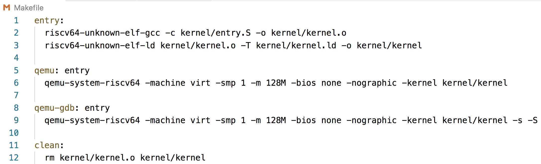
In the directory containing the Makefile, make qemu compiles, links, and boots the kernel with QEMU; make qemu-gdb enters debugging mode; and make clean removes the build artifacts (quite similar to Maven's lifecycle phases, isn't it?).
At this point the project structure is initialized and the build flow is simplified, laying the groundwork for further development (project: https://github.com/open-program/minos).
Running on a development board (optional)
With the kernel running in the QEMU emulator, the next step is to try it on a development board to verify that the kernel program works on real hardware. Below I use the Allwinner D1 RISC-V development board as the example. I mainly share the general approach here; if you are interested in the specifics, leave a comment below.
The overall approach stays the same: produce serial output by writing to a specific address. The difference is that in the emulator, QEMU loads the kernel program into the specified memory, while on real hardware this process is not so simple. We need to know who loads the kernel, where on disk it is loaded from, and at which memory address it is loaded.
To answer these questions, we first need to understand the board's boot flow. On the Allwinner D1 board, the full boot flow has several steps:
- After power-on, run the instructions burned into ROM (this step is the same as on QEMU)
- Load the SPL (Second Program Loader, also called boot0) from the start of flash storage (similar to a hard drive) into SRAM (static RAM) and run it
- The SPL loads OpenSBI (Open Supervisor Binary Interface, a binary interface for the operating system) and u-boot (a bootloader) into DRAM (dynamic RAM) and runs them
- u-boot loads the operating system kernel from the boot partition of flash into DRAM and runs it, completing the boot flow
Given this boot flow, we can decide at which step to step in so our kernel program gets loaded and runs. The options are:
- Option 1 (not feasible): shorten the boot flow to ROM -> Kernel. Experiments showed it fails to boot, because during boot the SPL initializes the clock, memory, serial port, and other hardware. Skipping this step would require implementing that initialization in the kernel program
- Option 2 (not feasible): shorten the boot flow to ROM -> SPL -> Kernel. However, this board's SPL strictly verifies OpenSBI and u-boot, so it boots normally but cannot boot a custom kernel program
- Option 3 (feasible): use a tool to load the kernel program directly into memory and run it. On the Allwinner D1 board, the xfel tool can, in FEL mode, initialize memory, load the kernel into memory, and run it (xfel -> Kernel). But this feels more like running a program than like bare metal powering on and running an operating system directly
- Option 4 (feasible): follow the standard boot flow (ROM -> SPL -> OpenSBI -> uboot -> Kernel), but replace the board's bundled operating system with our own, so the kernel runs within the complete boot flow
Here is how Option 4 is implemented. The main steps are:
1. Build the standard boot image: First, follow this article to modify u-boot's boot command configuration, replacing the complex commands originally used to boot Linux with a simple address jump so it can boot our homemade kernel. Then build the boot image (containing the SPL, OpenSBI, u-boot, and the bundled Tina OS) according to the D1 chip's official documentation
2. Kernel code changes: This step adapts our code to the real hardware. The chip manual gives the serial port address as 0x02500000, so the serial port address in entry.S needs to be changed.
Note, however, that the kernel binary built earlier is an ELF file. In the emulator, QEMU parses the ELF header information (such as the address 0x80000000 defined in the linker script) and runs it, but real hardware cannot recognize this information, and the redundant header data would actually get in the way of running the first instruction. So we strip this metadata and produce a clean binary file, kernel.bin, with this command:
riscv64-unknown-elf-objcopy -O binary kernel/kernel kernel/kernel.binWith the metadata removed, another question comes up: how do we determine the exact memory address the kernel is loaded at? The answer is that u-boot decides it. When the D1-H board boots, u-boot loads the kernel at memory address 0x45000000 (in DRAM), so the address declaration in the linker script kernel.ld does not need to change.
3. Replace the image and pack: Replace boot.img in the standard boot image with our kernel.bin and run the pack command. This produces a standard boot package containing our own kernel.
4. Flash and run: Flash the package to the board's flash storage (LiveSuit on Linux, PhoenixSuit on Windows; see the documentation). Power on the board, connect it to the development machine over the serial port, and in the serial terminal you can see the kernel running successfully after the machine boots.

Note: in the left image, the three-colored wires at the top right are the serial connection to the board, and the type-c port at the bottom left is the power port. In the right image, the last line of the log is printed by our homemade kernel; the rest of the log comes from the other boot programs in the standard boot flow.
Summary
This chapter completed the first step of building an operating system from scratch. We ran the kernel's first instruction in both an emulator and on real hardware, and printed characters over the serial port without depending on any library. Along the way we covered the basic RISC-V instructions and registers, compiling and linking, and how to use QEMU, the serial port, GDB, and Make, and we now have a working development environment for the operating system.
Rather than an operating system, the current MinOS kernel is really just a simple bare-metal program: it only manages to run itself and does none of the work of an operating system. So the next chapter will start discussing the responsibilities of an operating system and gradually add features to the kernel.

感觉被震撼到了,强
博主你好。我照你的教程在Windows 10上做了一遍,发现运行
```
qemu-system-riscv64 -machine virt -smp 1 -m 128M -bios none -nographic -kernel kernel
```
无法输出“Hello”字符串,只会弹出5行[0x7FF8ADE95A60] ANOMALY: meaningless rex prefix used(每行的地址不同),是什么原因呢?
哇我在找的就是这个 感谢博主 博主还在更新吗
暂时没更新了,不过有问题可以交流
你好呀
强的!!